Customize BeagleV-Fire Cape Gateware Using Verilog#
This document describes how to customize gateware attached to BeagleV-Fire’s cape interface using Verilog as primary language. The methodolgy described can also be applied when using other HDL languages.
It will describe:
How to generate programming bitstreams without requiring the installation of the Libero FPGA toolchain on your development machine.
How to use the cape Verilog template
How to use the git.beagleboard.org CI infrastruture to generate programming bitstreams for your custom gateware
Steps:
Fork BeagleV-Fire gateware repository on git.beagleboard.org
Create a custom gateware build option
Rename a copy of the cape gateware Verilog template
Customize the cape’s Verilog source code
Commit and push changes to your forked repository
Retrieve the forked repositories artifacts
Program BeagleV-Fire with your custom bitstream
Fork BeagleV-Fire Gateware Repository#
Important
All new users need to be manually approved to protect from BOT spam. You will not be able to fork the Gateware Repository until you have been approved. A request to the forum may expedite the process.
Navigate to BeagleV-Fire’s gateware source code repository.
Click on the Forks button on the top-right corner.

Fig. 601 BeagleV-Fire gateware repo fork button#
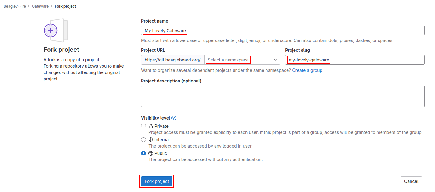
On the Fork Project page, select your namespace and adjust the project name to help you manage multiple
custom gateware (e.g. my-lovely-gateware). Click the Fork project button.

Fig. 602 Create gateware fork#
Clone the forked repository#
git clone [email protected]:<MY-NAMESPACE>/my-lovely-gateware.git
Where <MY-NAMESPACE> is your Gitlab username or namespace.
Create A Custom Gateware Build Option#
BeagleV-Fire’s gateware build system uses “build configuration” YAML files to describe the combination
of gateware components options that will be used to build the gateware programming bitstream. You need
to create one such file to describe to the gateware build system that you want your own custom gateware
to be built. You need to have one such file describing your gateware in directory custom-fpga-design.
Let’s modify the ./custom-fpga-design/my_custom_fpga_design.yaml build configuration file to
specify that your custom cape gateware should be included in the gateware bitstream. In this instance will
call our custom cape gateware MY_LOVELY_CAPE.
HSS:
    type: git
    link: https://github.com/polarfire-soc/hart-software-services.git
    branch: master
    make_clean: 1
gateware:
    type: sources
    build-args: "M2_OPTION:NONE CAPE_OPTION:MY_LOVELY_CAPE" # ①
① On the gateware build-args line, replace VERILOG_TUTORIAL with MY_LOVELY_CAPE.
Note
The custom-fpga-design directory has a special meaning for the Beagleboard Gitlab CI system. Any build configuration found in this directory will be built by the CI system. This allows generating FPGA programming bitstreams without the requirement for having the Microchip FPGA toolchain installed on your computer.
Rename A Copy Of The Cape Gateware Verilog Template#
Move to the cape gateware source code#
cd my-lovely-gateware/sources/FPGA-design/script_support/components/CAPE
Create a directory that will contain your custom cape gateware source code#
mkdir MY_LOVELY_CAPE
Copy the cape Verilog template#
cp -r VERILOG_TEMPLATE/* ./MY_LOVELY_CAPE/
Customize The Cape’s Verilog Source Code#
ADD_CAPE.tcl if you want to modify how the cape interfaces with the rest of the gatewareTip
HDL subdirectory will automatically be pulled into the project by the build system.Customize The Cape’s Verilog source code#
We will add a simple Verilog source file, blinky.v, in the MY_LOVELY_CAPE/HDL directory. Code below:
`timescale 1ns/100ps

module blinky (
  input  clk,
  input  resetn,
  output blink
);

reg [22:0] counter;

assign blink = counter[22];

always @(posedge clk, negedge resetn)
begin
  if(~resetn)
  begin
    counter <= 23'b0;
  end
  else
  begin
    counter <= counter + 23'b1;
  end
end

endmodule
Let’s connect the blinky Verilog module within the cape by editing the CAPE.v file (we’re still in the HDL subdirectory).
Add the instantiation of the blinky module:
//--------P9_41_42_IOPADS
P9_41_42_IOPADS P9_41_42_IOPADS_0(
        // Inputs
        .GPIO_OE  ( GPIO_OE_const_net_3 ),
        .GPIO_OUT ( GPIO_OUT_const_net_3 ),
        // Outputs
        .GPIO_IN  (  ),
        // Inouts
        .P9_41    ( P9_41 ),
        .P9_42    ( P9_42 )
        );

//--------blinky
blinky blinky_0(                // ①
        .clk     ( PCLK ),      // ②
        .resetn  ( PRESETN ),   // ③
        .blink   ( BLINK )      // ④
        );

endmodule
① Create a blinky module instance called blinky_0.
② Connect the clock using the existing PCLK wire.
③ Connect the reset using the exisitng PRESETS wire.
④ Connect the blinky’s blink output using the BLINK wire. This BLINK wire needs to be declared.
Add the BLINK wire:
wire           PCLK;
wire           PRESETN;
wire           BLINK;                   // ①
wire   [31:0]  APB_SLAVE_PRDATA_net_0;
wire   [27:0]  GPIO_IN_net_1;
① Create a wire called BLINK.
//--------------------------------------------------------------------
// Concatenation assignments
//--------------------------------------------------------------------
assign GPIO_OE_net_0  = { 16'h0000 , GPIO_OE };
assign GPIO_OUT_net_0 = { 16'h0000 , GPIO_OUT };
We are going to hijack the 6th I/O with our blinky’s output:
//--------------------------------------------------------------------
// Concatenation assignments
//--------------------------------------------------------------------
assign GPIO_OE_net_0  = { 16'h0000,  GPIO_OE[27:6],  1'b1,  GPIO_OE[4:0] };    // ①
assign GPIO_OUT_net_0 = { 16'h0000, GPIO_OUT[27:6], BLINK, GPIO_OUT[4:0] };    // ②
① Tie high the output-enable of the 6th bit to constantly enable that output.
② Control the 6th output from the blink module through the BLINK wire.
Edit The Cape’s Device Tree Overlay#
/dts-v1/;
/plugin/;

&{/chosen} {
        overlays {
                MY-LOVELY-CAPE-GATEWARE = "GATEWARE_GIT_VERSION";   // ①
        };
};
① Replace VERILOG-CAPE-GATEWARE with MY-LOVELY-CAPE-GATEWARE.
MY-LOVELY-CAPE-GATEWARE being visible in /proc/device-tree/chosen/overlays at run-time,Commit And Push Changes To Your Forked Repository#
Move back up to the root directory of your gateware project. This is the my-lovely-gateware directory in our current example.
Add the my-lovely-gateware/sources/FPGA-design/script_support/components/CAPE/MY_LOVELY_CAPE directory content to your git repository.
git add sources/FPGA-design/script_support/components/CAPE/MY_LOVELY_CAPE/
Commit changes to my-lovely-gateware/custom-fpga-design/my_custom_fpga_design.yaml
git commit -m "Add my lovely gateware."
Push changes to your beagleboard Gitlab repository:
git push
Retrieve The Forked Repositories Artifacts#
build-job:archive. This will result in an artifacts.zip file being downloaded.
Fig. 603 gateware pipeline#
Program BeagleV-Fire With Your Custom Bitstream#
Unzip the downloaded artifacts.zip file. Go to the gateware-builds-tester/artifacts/bitstreams directory:
cd gateware-builds-tester/artifacts/bitstreams
<IP_ADDRESS> with the IP address of your BeagleV-Fire.scp -r ./my_custom_fpga_design beagle@<IP_ADDRESS>:/home/beagle/
On BeagleV-Fire, initiate the reprogramming of the FPGA with your gateware bitstream:
sudo /usr/share/beagleboard/gateware/change-gateware.sh ./my_custom_fpga_design
Wait for a couple of minutes for the BeagleV-Fire to reprogram itself.
tree /proc/device-tree/chosen/overlays/

Fig. 604 gateware lovely overlay#
